Q: What did happen in Lille in 1996?
A: MOSS conference was held, and I gave a presentation.

congrés euromoss
école supérieure de commerce de lille
29-31 octobre 1996
Road Designing in UVATERV
presented by
Zsolt Pintér
UVATERV - Hungary
ABSTRACT
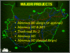
Major projects designed by UVATERV
|
The first project on MOSS (dsign for approval) |
|
The first toll motorway section in Hungary |
|
15 km long highway on plain and hilly terrain with interchanges and several special tasks |
|
Just finished work, including resurfacing, construction of the 2nd carriageway, renewing existing interchanges, design of new sections of motorway, and numerous new problems |
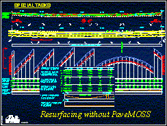
Special tasks
- Stabilisation of a cross-valley under the embankment with ´stairs-cutting´
- Demonstrating visualisation option of MOSS for an exhibition
- Designs of resurfacing according to special requirements
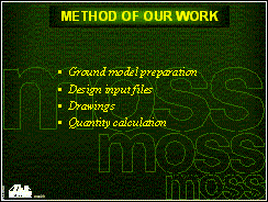
Method of our work
- preparation of ground model using our string labelling convention
- triangulation and contouring with boundary
- design input files
- preparing plan and long section DPFs
- cross sectioning
- quantity calculation using several boundaries
- output area and volume strings, completing tables in MS EXCEL
- archiving
IntroductionI have been working for UVATERV since 1990. Nobody have heard anything about MOSS at that time. Young engineers worked on PCs with AutoCAD and MicroPiste. The primary design package was the MACAO system on MicroVAX workstation. After the political change in Hungary, UVATERV had to make efforts to maintain its leading role. New computers, new, young staff and new softwares were necessary for staying alive. MOSS determined the future of UVATERV. Ferenc Szent-Iványi our CAD-CAE manager saw MOSS first in 1991 during a demonstration. Our management compared the system with others and found it to be the most suitable for our requirements. The first licence was purchased as part of a development programme organised by the National Committee for Technological Development, sponsored by the Hungarian Government. UVATERV´s requirement sparked off by the limitations in our existing design systems. UPM has given us the means to create programs which will automate much of repetitive work in highway design, to control complex data import and export routines and to generate designs and drawings which adhere to local standards. We managed to demonstrate on the M3 motorway project that the great advantage of the system is not only the improved quality of design that we can produce, but the fewer man-days we need to do it. If UVATERV had not obtained the M3 project and had not ordered two MOSS licences in 1992, I probably would not take this presentation here. |
 |
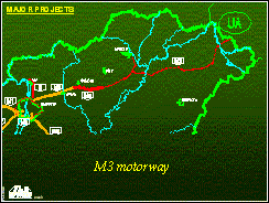
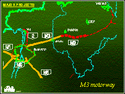
Major projectsM3 motorwayFollowing initial MOSS training, our first project was to design new sections of the M3 motorway. This motorway is 70 km long and ends at Gyöngyös today. The Ukrainian border is 230 km far from there. M3 will have to link Budapest with the north east industrial territories, the major cities -Miskolc, Debrecen, Nyíregyháza- and east of Slovakia, Ukraine. An overall plan for approval had to be produced. Many changes of alignment were called for, in large part due to local political pressure, and MOSS allowed us to react to these requirements and carry out the rapid amendment and redesign needed. We introduced MOSS in stages throughout the project, to aid staff learning. In the end the new system was used to design 153 km of the total works. The design work commenced in May 1992, the last section finished by the end of January 1993. We were beginners, but the result was quite nice. |
   |
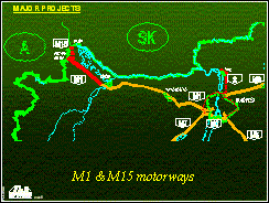
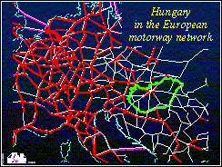
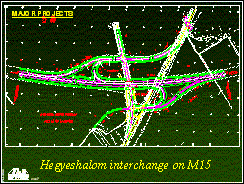
M1 & M15 motorwayM1 is the first toll motorway in Hungary. It was a detailed design, a real hard work. We had to work out every little detail. This project contained the last 40 km long missing part of the existing motorway from Győr to the Austrian border and the new M15 motorway from Hegyeshalom to Rajka. The importance of this motorway is plain for everybody if we look at the Europe map. This part connects the Hungarian motorways with the European network. Four interchanges, a rest area, several crossing and parallel roads were designed. The last 5 km of the existing right carriageway was resurfaced. We used the isopachyte contours first here. New macros and UPMs have been developed to simplify the design process of the special Hungarian superelevations, the interchange ramps, the ditches, the subgrades, the volume calculations, etc. MOSS accelerated the work very much. The 40 km was divided into four construction section. The effective design procedure took five weeks per section. The motorway was opened to traffic in January. It is very beautiful (and expensive). In a word it seemed we have become more and more experienced MOSS users. |
   |
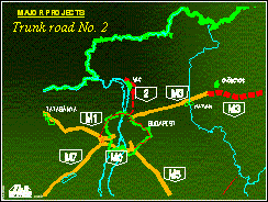
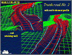
Trunk road No. 2The trunk road No. 2 has been a real nerve racking work. The Vác bypass is only a 15 km long highway but never ends. The client ordered the detailed designs in August 1994. We could make the full documentation in time, but since then the pavement layers have been changing, some interchanges have reshaped, little earthroads have appeared, that is the whole project is changing continuously while the road itself is being constructed. But MOSS does not care about our problems. Quickly produces the new drawings, the changed quantities, the eleventh variation of cross sections and does not understand why we are nervous. |
  |
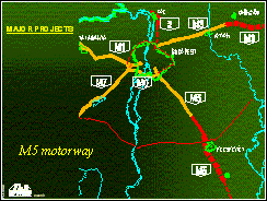
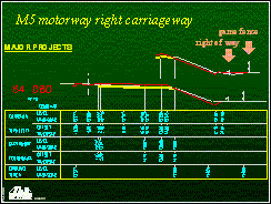
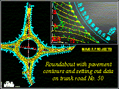
M5 motorwayThe M5 motorway was the largest project on MOSS by now. The detailed designs were divided into four parts according to the four construction sections. The first section was the existing part of the motorway. An interchange had to be reconstructed and resurfacing were designed where the pavement was in bad condition. This section and the following one was about 30 km long. On the second section where only the left carriageway was built, we designed the right carriageway. Connected interchange ramps and rest area ramps were realigned. The shoulder of existing carriageway was widened because of the designed noise screening walls at certain places. Designing the ditch and the interface was the most difficult problem for us and for MOSS, too, because the game fence was built on the right side many years ago simultaneously with the left carriageway. This fence was the edge of our designed cross sections and this width was quite narrow. There were two conditions: the earthwork cannot reach the fence and the drainage problem had to be solved. Several profiles were defined in the complex DESIGN and INTERFACE options and MOSS was asked to select the optimal solution along the full length of the section. The third part -Kecskemét bypass- and the fourth part was 17 and 23 km long, and included 5 interchanges, 2 rest areas, 2 new trunk road alignments a roundabout on each and several crossing and parallel roads. It was a new and interesting task to produce complex drawings about intersections with setting out data and pavement contours. The whole M5 project took one and half year on three MOSS sites. The progress was very slow in the first six month, because the client cared only about his newly invented unique and uniform format for the whole documentation. According to the contract every document such as drawings, reports, calculations, etc. had to be handed over to the client on disks, too. We had no choice, we had to put on all enhancements, work out the smallest details, control the quiantities many times. In addition, the client required a four stage design process: preliminary, intermediate, final and ´good for work´ stages. Clever input files, macros and UPMs helped us to modify the model file quickly according to the client's or Independent Engineer's remarks and release the revisioned documents in time. |
   |
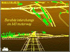
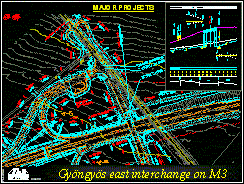
M3 motorwayNow we are working on the M3 project. I got a 9 km long part of the motorway with an interchange, a rest area, a game crossing and earthroads. The ground model preparation took two weeks and the design process took only one, because I wanted to go on holiday and before it I had had to supply the engineering team with drawings, data and other information. Since I came back my only task is modifying the details according to the requirements. Now I think there is no highway engineering problem that I cannot answer. |
  |
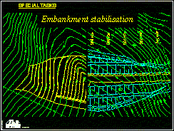
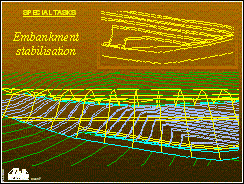
Special tasksEmbankment stabilisationThe task was the following. The designed highway crossed a valley on a hilly terrain. The road would be on embankment, but the crossfall of the existing ground was very steep, consequently a terraced formation as a cogging was proposed under the embankment and a stone obstacle at the lower end of the valley. I had to calculate the cut and fill volumes. First I created a straight master string in the axis of the valley. I raised it step by step using half meter interval and created interface strings with zero slopes. These interface strings were nearly the same as contours. Then the lower strings of each stairsteps were created by a simple 110 option. The profile of the obstacle was designed backward from the original interface strings of the road. The little triangles at both end of a stairstep were shaped just for the show. Finally the editing, the trimming of the strings closes the UPM. After triangulation using PRISM option the volumes can be calculated easy. |
   |
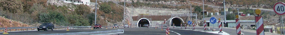
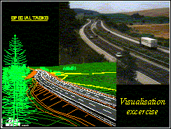
Visualisation excersiseWe never have time for making spectacular 3D pictures in MOSS. Once I was asked to produce a view about an existing part of M1 motorway and they provided me a photo. The aim was to put the photo and the MOSS view side by side in an exhibition. I do not want to talk about it too much, it was not difficult at all. I digitised the terrain from maps, entered the motorway in MOSS using the old designs and tried to find the eye and the target point. |
 |
Resurfacing without PaveMOSSAs mentioned above a long part of M5 motorway had to be resurfaced. Along the carriageway each surveyed cross section contained three important points for the design. These points were on the pavement, of course. I have created three strings from them. In Hungary, in case of dual carriageways the axis of the superelevation is the inner edge of the pavement. Using the required crossfall I projected the levels from the three strings to the axis. I got three strings with different levels below or above the axis. The "cover" string was created by using the highest point of the strings in each chainage. Then the "cover" string was raised by the minimum thickness of resurfacing. The vertical alignment was designed in the next step. Where the designed master string was under the "cover" string scraping would be needed. Finally the strings of the new pavement were designed. We selected a proper scale for the long sections. The three original and the three new string were displayed. In the plan drawing window we drew up the isopach contours and indicated the scraping with dashed lines. |
 |
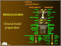
Method of our workGround model preparationThe ground survey data are passed to us in three ways, but unfortunately none of them is in the proper format. The worst is when we get a set of points in a file and a sketch how to link them. It could be even worse if we should type in the co-ordinates, too. We are happier when the surveyors hand over a DXF file. It seems to be better, but these files usually contain huge amount of surplus information and the important polylines are linked or layered incorrectly, etc. Even the ITR program, the most popular software of surveyors in Hungary, creates only single lines instead of polylines. The amending of ground model takes a long while. We developed a program to join the two or three points strings which have common start or endpoint. Usage of this program needs three steps.
When it have finished a model file compression is required, of course. We managed to teach only few immediate colleagues how to produce proper DXFs for MOSS. They do not use MOSS, because they have usual process of survey and they do not want to change. (I think they have not seen the TopoMOSS yet). Thus the only solution is a fine DXF in the required format. For the sake of it we determine the layer names and other circumstances, and developed a uniform string labelling for ground models. Other companies have already joined to this convention. To help this method we offer them a macro. It draws up every strings which have conventional label. This macro is inserted in all our plan drawing process. The lines, macrolines, symbols and line widths are correspond to the usual key from the preMOSS era. |
  |
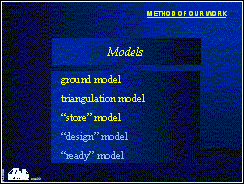
Triangulations and contouringWe consider the ground model preparation completed, when the triangulation is created without any warning, namely there is not any intersection or double point in the model. Our plan drawings show the contours with three line types, because we use three intervals: 5.0 m, 1.0 m, and 0.5 m. It means contouring needs two 970 option. First the 5.0 m and the 1.0 m contours are made and the 1.0 m contours are deleted immediately. Then the 1.0 m and the 0.5 m contours are created normally. If the curve fitted contours are not beautiful, we insert additional points in the ground model. After contouring we create a boundary string manually. This boundary surrounds the area where we do not wish contours to appear. We have three models at this step. A ground model, a triangulation model and a model called "store" for strings created manually. The "store" model is also for the alignments. We use two further models for designing, a "design" model and a "ready" model. |
 |
Design input filesEach object (interchange, rest area, earthroad, etc.) is created by an input file. An "object" file creates every string of an object in the "design" model, and then copies the strings into the "ready" model. If all the objects are ready a completing input file edits the connecting places in the "ready" model. We use several macros in these files, as many as we can, but we need two UPMs, too.
|
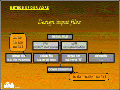 |
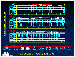
DrawingsWhen we are ready with designing, we can draw plan and long sections. We draw strings exclusively from the "ready" model. Only two smart UPMs and simple parameter files are needed for drawings. If the client orders a unique drawing format we develop a new UPM or modify one of the existing ones to satisfy the new requirements. We prefer other software for enhancing. Only a few enhancement is placed on the drawings in MOSS. It has the following reasons: we have less workstations than PCs and the deadlines are very close every time, so it is more effective if more people make the enhancement on PCs than only one in MOSS. Another reason is that Hungarian characters are available only on two workstations. Although we have software font files with our special characters, we seldom use these fonts because of the above reasons. However the cross section drawings do not need further enhancement. They are completely ready when plotted from MOSS. The title box, the codification, the remarks, etc. are put on. We use a macro for drawing and input files for sectioning everything. Cross sections need more than one section model. In a single cross section we display usually four section strings, but the number of strings may be twelve or more. The cross section drawing formats of each project are slightly different. It means so many projects we had so many macros have been developed. |
 |
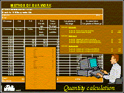
Quantity calculationThe next unpleasant task is the quantity calculation. The latest and probably the best method for the calculation is worked out a year ago. The "quantity" input file creates several boundaries, such as boundary of earthwork, pavement, slopes, shoulders and everything, then calculates the earthwork volumes and triangulates the designed strings of the "ready" model. Finally prints the volume and area strings as well as every important plan and slope areas with many comment lines into an output file. The bill of quantities and other tables are made by a table editor. Data supplyThe construction companies do not use MOSS yet in Hungary. They are satisfied with DFX files or simple string listing as setting out data. Certainly they also get printed matter, but nowadays more and more of them requires disks, too. ArchivingWe archive the data when a project completely finished and the road is opened to traffic or when we are out of disk space. Archiving is usually a full copy of the project to tapes. There is a much more economical procedure. If we archive only the ground model and the "store" model from the model.fil file and the input files and the parameter files, we can save storage space. |
 |